All CPUs needs to be powered on correctly, and m68k is no different. Just supplying power is not enough, and the CPU needs some things to ensure registers are cleared, and CPU prepared to start executing. But before that, let us look at how an CPU actually do stuff. Now, this will be very general, and all CPUs differs somewhat, but in general they work in the same way on an higher level.
The program counter
CPUs have what is called a Program Counter. It is an small memory area in the CPU called a Register. There are several registers in an CPU, but the program counter is where the CPU keeps an very important thing, the address to where it can find the next instruction to execute. At start, the counter start at an reset vector address defined by the architecure itself. In our case (m68k) at hex 00000000. C64 6502 CPU uses hex address FFFC. When accuiring the adress, the CPU reads the data at that address, and expects it to be an valid instruction. This brings us to the next core concepts on an CPUI, namely the instruction set.
Instruction set
We have all heard it. ISA, instruction set, RISC/CISC, ARM, MIPS etc. What it all boils down to is a set of instructions an CPU can accept and the format of these instructions. This is an HUGE topic, and differs substancially between various architectures. But to make it understandable lets us make it a little bit simplified. When a CPU starts executing it expects an instruction at it’s reset vector. Now, since we are talking m68k, we are going to use that as ann general description.
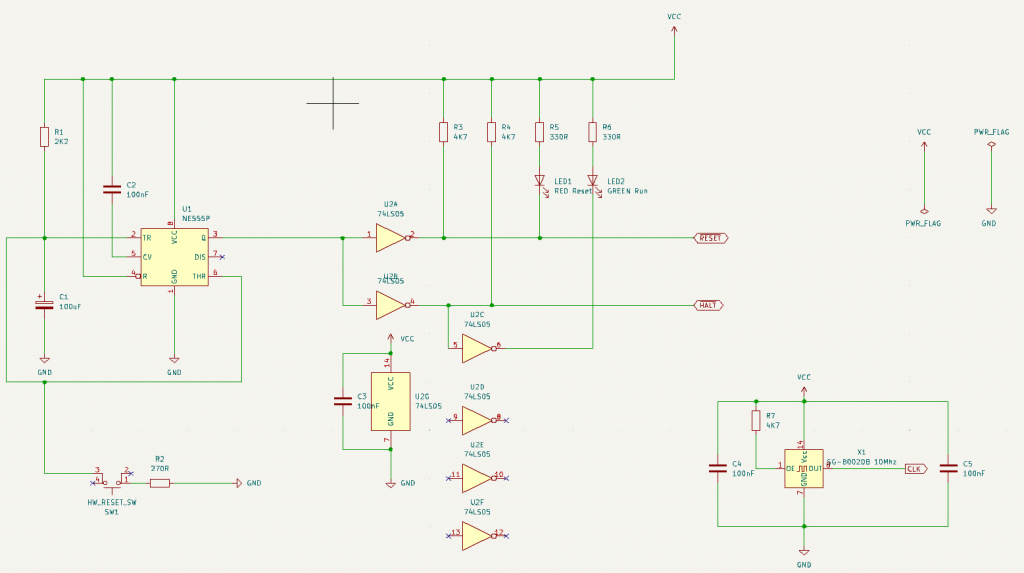
MC68010 reset circuit
The MC68000 reference manual states the following:
RESET is asserted externally for the initial processor reset. Subsequently, the signal can
be asserted either externally or internally (executing a RESET instruction). For proper
external reset operation, HALT must also be asserted.
When RESET and HALT are driven by an external device, the entire system, including the
processor, is reset. Resetting the processor initializes the internal state. The processor
reads the reset vector table entry (address $00000) and loads the contents into the
supervisor stack pointer (SSP).
The RESET instruction causes the processor to assert RESET for 124 clock periods to
reset the external devices of the system. The internal state of the processor is not
affected. Neither the status register nor any of the internal registers is affected by an
internal reset operation. All external devices in the system should be reset at the
completion of the RESET instruction.
So what his means in effect, an reset needs 124 clock cycles to reach valid state. This have some minor mathematical implications on an reset circuit that depends on clock speed. What we know is that we need to drive the RESET and HALT pins of the CPU low for 124 clock cycles. In my initial design I will run at 1 MHz (for easier debugging), but in the end I will try to reach 12 MHz, so 12MHz is what we are going to use.
12MHz means that during one second, we have an clock period transitioning going from high to low to high six million times. Keep in mind, a cycle is not jus going low to high, it is going low-high-low. This then needs an multiplication with 124 cycles to define the actual time the RESET and HALT needs to be asserted before the CPU is ready to execute code. In practical term, as shown in the diagram in the documentation, we need to keep these pins asserted >100ms. In my design, we end up in around 200ms. One can use whatever time above this, but 200ms is more than enough.
The Swiss army knife of ICs: 555 timer, we salute you!
If you are new to electronics in general, this is where you go to Youtube and search for “555 timer”. This is an versatile chip that have an exceptional wide range of usecases. But for this purpouse it will be used as an monostable circuit, giving us the 200ms delay before letting the CPU execute. So, what we are trying to accomplish with the circuit is the very simple:
- At power on, we have a pinout of the circuit at low (0v)
- After 200ms, we transition to high (+5v)
Now, this is quite simple in terms of the 555 timer, but the m68k causes some things to consider caused by the fact that external device could cause RESET/HALT, in effect sharing the physical pins. But more on that later.
End result: